Skip to content
logo blue
Control points on the automatically generated surface -left

Case Studies

Published on Jan. 1st 2024

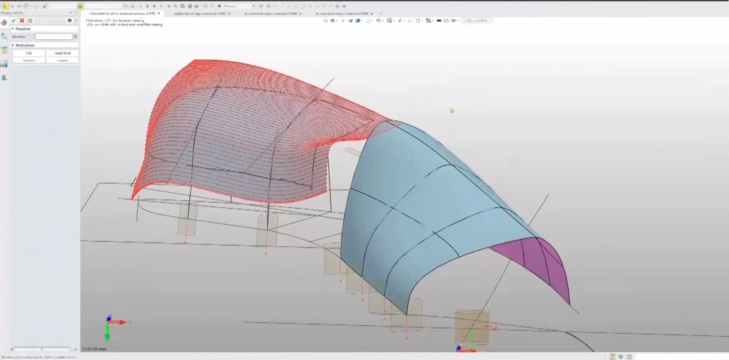
Mastering Scan to CAD: Starting with Tips for Preparing Scans to Complete CAD Models

SHINING 3D’s ambassador Adrian Melia is a UK-based mechanical design engineer with over 40 years of professional experience, 30 of whom are focused on plastic injection molded parts for passenger car interiors. He presented a step-by-step guide to scan to CAD process during the latest webinar. Now, read on for some highlights.

Scan to CAD workflow is the process of scanning a physical object and inputting the data into CAD software. The benefit of reverse engineering an object based on 3D scan data to create CAD models is that it provides an accurate foundation on which designers and engineers can build and improve their models-instead of starting from scratch. It also makes sure that your designed product fits properly to an existing object. However, how does it work?

SHINING 3D’s ambassador Adrian Melia is a UK based mechanical design engineer with over 40 years professional experience and 30 of those focused on plastic injection molded parts for passenger car interiors. He presented a step-by-step guide of scan to CAD process during the latest webinar. Now, read on for some highlights.


Download brochure

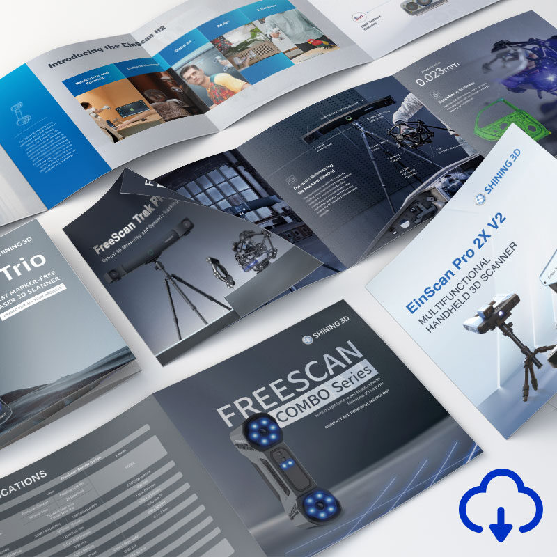
Discover the product you're looking for

- Full specifications
- Using scenarios
- Key features
- Even comes with a bundle!

Tips for Preparing a Scan to Use as a Template


Getting the scan data is the first step. If you are using a 3D scanner to create templates for CAD models, you need to be aware of the limitations of the scanner. Small and deep holes are the main challenge because the only part of the inner wall that you will get scanned is just around the top.


3D Scanning Tip for Holes

3D scanning for holes

A tip is to plug the hole, leaving some of the plug exposed, and the exposed part will be easy to scan.

Plug the hole
Plug the hole

3D Scanning Tip for Deep Grooves


Deep grooves are similar. Unlike holes, grooves are not easily plugged, so keeping the 3d scanner’s line of elements parallel to the grooves will capture more data.

When the scanner is angled perpendicular to the groove
 
When the angle of the scanner is parallel to the groove
When the scanner is angled perpendicular to the groove

*SHINING 3D FreeScan Pro is the best option for scanning object with holes and deep grooves.

Another tip is to fasten flexible or distorted parts down so that they maintain the correct shape.

After simple cleaning of scan data, mesh is carried out. Adrian recommends saving it as non-watertight and minimizing use of optimizations, such as filling holes, smoothing, as this will make the mesh a different shape from the physical part.


Save as Non-watertight for Keeping the Organic Shape

Scanning data before filling holes
 
scanning data after filling holes-not the right shape
Scanning data after filling holes-not the right shape

Let’s look at an example of a scan: a handle moulding done with EinScan-SP Desktop 3D Scanner. It was a black glossy injection mold that had been sprayed with dry shampoo, and EinScan-SP Desktop 3D Scanner helps us get accurate data when using tripod and turntable marker mode.

Scanning data of the handle moulding

Scanning data of the handle moulding


Construction Process of CAD Models


Adrian uses simple, generic techniques for building CAD models: The STL file is first imported into the CAD software-ZW3D.


A step that makes a lot of sense is aligning the 3D scan data with the CAD construction axis. This makes it easier to create accurate and detailed CAD models from the 3D scan data. when you want to align other scan that you import, you can assemble them together like CAD entities in an assembly. Then create a plane through the scan and create a cross section, which is used as the basis for building the sketch. Tracing the section using lines, arcs and splines to make a refined version of the section. Repeating this as necessary in different positions and then build CAD entity surfaces using the sketches.


Adrian shows this workflow step by step with examples in the webinar to make the explanation more specific.


Techniques for Making Simpler Surfaces through Clouds of Points


Adrian also shows the difference between surfaces generated using automatic tools and manually generated surfaces. It can be seen clearly that the number of control points on the manually generated surface is far fewer than the number on the automatically wrapped patch. In addition, there are many ripples on the edge of the automatically generated surface.

Control points on the automatically generated surface -left
 
Control points on the automatically generated surface
 
Automatically generated surface-left, manually generated surfaces-right
 

A much more controlled way of creating a surface on a point cloud was introduced in this webinar. Rather than using the point cloud itself as the target for the wrapped surface, Adrian generated a set of points just in the patch that he wants the surface to cover, and then selecting those and choosing to wrap a surface with a U&V degree of three.

Creating a surface on point cloud
 Creating a surface on point cloud 
 

This is an overview of the basic process from scan to CAD with useful tips. You may find more operation details in the playback video.

If you found this content useful, please follow us so you won’t miss out on more information.

*All images of this article are based on the webinar Using 3D Scanned Models as Templates for Building CAD Models.

SP

EinScan SP V2

The EinScan SP V2 is designed to bring ideas to life through 3D scanning, making it accessible for every creator. It features five alignment modes, enhancing the scanning experience by providing greater flexibility and accuracy in capturing detailed 3D models. 


  • Fast Scanning Speed
  • 5 Alignment Modes for Better Scan Experience
  • Stable and Reliable Results